Table Of Content
A DSM is a square matrix, representing linkages between the system elements. The system elements are often labeled in the rows to the left of the matrix and/or in the columns above the matrix. These elements can represent for example product components, organization teams, or project activities. To meet the challenges of scaling systems in size, scope, and complexity,it is useful to look at new approaches and theories to analyze, design,deploy, and manage these systems. A Design Structure Matrix(DSM) is an approach that supports the management ofcomplexity by focusing attention on the elements of complex systems andhow they relate to each other.
Design in DSM
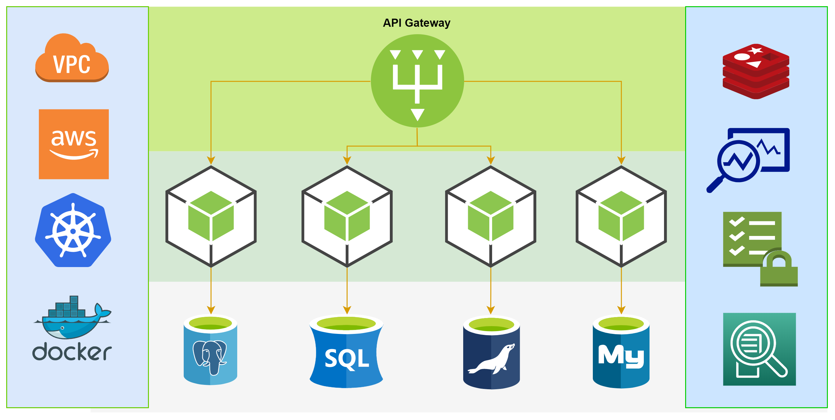
In a microservice architecture, services with high betweennesscentrality may have considerable influence within the system by virtue oftheir control over information passing through the system. They are alsothe services whose removal from the network will most disruptcommunications between other services because they lie on the largestnumber of paths between services. These services are typically correlatedwith critical data paths or single points of failure.

Will MACH enable new pricing models? (Microservices based, API-first, Cloud-native SaaS and Headless)
The best way to learn something is to apply it, and as I am a social learner I like to learn by doing things with other people, so we spun up a team at Ibbaka to explore applications. This work has expanded quickly over the last few weeks and I thought I would share some of our preliminary ideas here. In the sequential configuration, one element influences the behavior or decision of another element in a uni-directional fashion. For example, design parameters of element B are selected based on the design parameters of element A.
How to organize an economic value model for use in pricing design
Engineers design bionic “heart” for testing prosthetic valves, other cardiac devices - MIT News
Engineers design bionic “heart” for testing prosthetic valves, other cardiac devices.
Posted: Wed, 29 Jan 2020 08:00:00 GMT [source]
Examining any row in the matrix reveals all of the outputs from the element in that row (which are inputs to other elements). Looking down any column of the matrix shows all of the inputs to the element in that column (which are outputs from other elements). For example, in the figure below, reading across row 2, we see that element 2 provides outputs to elements 3 and 4. Reading down column 5, we see that element 5 receives inputs from elements 1, 3, and 4.
The datum in row i and column j of this matrix would be the answer of the i th person to the j th question. Sequencing re-orders the rows of a DSM to minimize the number of cycles.Intuitively, if we minimize the number of cycles in a process, we alsominimize the number of dependencies between steps, resulting in a moreefficient overall process. The first heuristic for obtaining a goodsequence is to find an ordering that minimizes feedback loops.
Clustering Components#
In the parallel configuration, the system elements do not interact with each other (at least not for the type of representation that is represented in the digraph). Understanding the behavior of the individual elements allows us to better understand the behavior of the system. If the system is a project, then system elements would be e.g. project tasks to be performed, and usually the relations would be the directed information exchange between the tasks. As such, task B is said to be independent of task A and no information exchange is required between the two activities. A simple wayto reduce the complexity of the software system is to reduce thecomplexity of the process it is trying to model. In many processes,the possibility of doing rework due to a failed step contributes to a lotof overhead in the system.
The MDM (Multiple-Domain Matrix) combines DSM and DMM into a complete system model. The DSM above shows that elements U1, U2 and U3 are used throughout the software. Although it takes some time to get comfortable with reading the matrices, there are a number of important advantages over UML.These key strengths are discussed below. That column 7 (P5) of row 13 (D3) is filled, for example, means that P5 is dependent on D3. A web site supports the DSM method, providing a DSM tutorial, publications, links to software, conferences, and training programs. DSM Knowledge will allow you to browse relevant publications and resources on the internet that will enable you to deepen your know-how and understanding on DSM.
Such modularity is helpful for controlling the emergence of system behaviors, modifying the system with minimal disruption, and increasing system robustness and resiliency, among other benefits. DSM also supports analyses of degrees of separation among elements, indirect and propagating effects, emergent behaviors, and social network analyses. In each section, a chapter introducing the technique is followed by a chapter of examples showing a variety of applications of that DSM type.
Why software dependencies matter
OS & OOS bases gridded furniture collection on architectural structures - Dezeen
OS & OOS bases gridded furniture collection on architectural structures.
Posted: Fri, 29 Dec 2017 08:00:00 GMT [source]
Ideally, software can be easily modified, is understandable, reliable and reusable. In practice, this often remains an ideal and over the course of time the software becomes increasingly rigid, opaque and fragile. In many cases the underlying cause is that the dependency structure of the software degrades over time. It is used to relate entities of one kind to each other, e.g. the tasks that constitute a complete project, and it can be used to identify appropriate teams, workgroups, and an ideal sequence of how the tasks can be arranged. The DSM above shows that element U2 is problematic, because in addition to incoming relationships it also has outgoing relationships.
One primary benefit of DSM is the graphical nature of the matrix display format. The matrix provides a highly compact, easily scalable, and intuitively readable representation of a system architecture. To keep the matrix diagram compact, the full names of the elements are often listed to the left of the rows (and sometimes also above in the columns) rather than in the diagonal cells. It is also easy to think of each diagonal cell as potentially having inputs entering from its top and bottom and outputs leaving from its left and right sides. The sources and destinations of these input and output interactions are identified by marks in the off-diagonal cells.
It is an extension of the classical Design Structure Matrix commonly used in systems engineering to describe the interfaces among components of a complex system. Because the architecture also contains an algorithm defining the order in which the software is run, a numbering system and lines depicting the process are introduced in the diagram. In this way, we are able to capture all of the data and process flow of an architecture in a single diagram. A DSM essentially shows the same information as a graph (q.v., graph theory), a node-link diagram, or many other possible representations.
In this way it is possible to display a system with thousands of elements and still keep the overview. First the design of a small example software application is shown in UML.Then step-by-step it is explained how using a DSM can help to understand and improve the design. Let’s turn our effort towards leveraging a DSM to analyze and improvesoftware architecture. Tyson R. Browning is Professor of Operations Management at the Neeley School of Business at Texas Christian University. His background includes industry experience with Lockheed Martin Corporation and several other organizations.
The cells on the diagonal represent the relationship of an element with itself and are usually empty. The number in the cell represents the strength of the relationship and is usually the number of dependencies between the elements. Tutorials, industrial use cases and further material to familiarize you with the ideas, concepts and capabilities of matrix-based complexity management. In-degree is a fairly simple metric tracking the number of edges directedinto a vertex in a directed graph.
The International DSM Conference provides a platform for researchers, practitioners, and developers of DSM‐related tools to exchange experiences, discuss trends, and showcase results and tools. It also acts as a forum for developing new ideas regarding complexity management in all kinds of industries and from many different perspectives. The conference mission is to enhance understanding and managing complex interdenpent relationships within and across product/process/people architectures.
Reviewing the general model with the team, we decided to layer value into this. Eventually we will need to change this into a more formal MDM (Multi Domain Model, but this is proving to be a useful way to pull skills and value together with process. Click on the image to see properly. This is easy to translate into RDF, which is important for Ibbaka as our Skill Graph and Value Graph are both represented in this way.
Please note that not all DSMs are written this way; while the convention of “row impacts column” prevails in some areas. This second convention is the transpose of the matrix from the first convention. Both conventions convey equivalent information, and anyone familiar with one convention can usually adapt to the other fairly quickly and easily. The reason for the existence of two conventions is that square-matrix-based methods sprung from at least two historical roots (discussed below). How do you get a thousand engineers to agree on the design a complex product in a timely way?


No comments:
Post a Comment